Background:

Many vehicles are equipped with a feature called "delayed accessory power" or "retained accessory power" (RAP) that allows the vehicle operator to listen to the radio and adjust the power windows for a short period of time after the keys are removed from the ignition lock cylinder. My 1998 crown victoria did not have this feature and I decided to investigate the possibilty of adding it.

In a vehicle with RAP, power is applied to the accessory circuits after the ignition is turned off until a preset time period elapses and is terminated immediatetly upon opening a door. 1995 and later crown victorias have a timer circuit built into the lighting control module (LCM) that provides +12V for around 30 minutes after the ignition is switched off and continuosly while the ignition switch is in the run or accessory positions. But, the demand lighting output behaves a little differently than the delayed accessory feature. Like the RAP feature, the output is hot whenever the key is in the run or accessory positions, and for a short period after the key is removed from the ignition. But unlike the RAP feature, opening a door or the trunk resets the demand lighting counter to 0 so that the output is powered for 30 additional minutes. If a door is left ajar for an extended period, the lcm will treat the output as a defective zone and the demand lighting output will still turn off after 30 minutes.

Connecting the radio ignition sense wire directly to the lcm demand lighting output would allow for the vehicle operator to listen to the radio for around 30 minutes after the keys were removed from the ignition. But if the radio was left in the on position, it would suddenly spring back to life immediatetly upon opening a door or popping the trunk lid.

To have the radio become live only after shutting off the ignition and terminate immediatetly upon opening the door, a pair of SPDT (single pole double throw) relays can be interfaced into the circuit. The actual door ajar switches in 1995+ crown vic are negative trigger switches, the lcm also has a door ajar output that provides a low current ground path whenever a door is opened.

In the circuit below, the radio is powered directly through a diode when the ignition is turned on. After the ignition is shut off, the relay coils recieve a constant +12V source on one of their coil wires for around 30 minutes. A ground path for the coil of the relay on the left is provided by the relay on the right so that the +12V demand lighting output is present on the radio sense wire. Opening a door energizes the relay on the right causing the ground path for the relay coil on the left to be broken and the radio sense wire to fall to 0 Volts.

If a momentary pushbutton switch were inserted into the circuit to provide a +12V source to pins 30 and 86 of the relay on the left, the relay would again latch to the on position powering the radio until a door was opened. Additionally a pushbutton switch would allow the vehicle operator to listen to the radio and operate the windows while a door was open as long as the switch was held while the windows were moving.

In binary, the latch logic here is:

Set (ignition sense wire)
Reset (door ajar wire)
Output (to radio and power window relay)
0 (0 Volts)
0 (No ground path present)
Previous state
0 (0 Volts)
1 (Ground path present)
0 (0 Volts)
1 (+12 Volts)
0 (No ground path present)
1 (+12Volts)
1 (+12 Volts)
1 (Ground path present)
Does not matter

Note that if Vcc is removed and later reapplied, the previous state output should default to 0.


Below is a relay setup that latches on when provided with a +12V pulse on the ignition switch wire and unlatches when provided with a +12V pulse on the domelight wire or when the demand lighting timer expires. This setup could be used to add RAP functionality to a recent crown vic since the output of the lcm that powers the domelight is a positive trigger circuit and will show +12V when a door is ajar. But the lcm is also equipped with a theater dimming feature that slowly fades the courtesy lights on and off. If the vehicle operator were to open and close the door very quickly, the relays may not unlatch.

In binary, the latch logic here is:

Set (ignition sense wire)
Reset (door ajar wire)
Output
0 (0 Volts)
0 (0 Volts)
Previous State
0 (0 Volts)
1 (+12 Volts)
0 (0 Volts)
1 (+12 Volts)
0 (0 Volts)
1 (+12 Volts)
1 (+12 Volts)
1 (+12 Volts)
Does not matter

Note that if Vcc is removed and later reapplied, the previous state output should default to 0.


Installation:


First part of installing the relay pair above is to tap the demand lighting output. As can be seen by the diagrams below, the demand lighting output is LG/O (light green with an orange stripe). It is present at multiple locations in the vehicle including the glovebox light, at the map lights on the headliner, and behind the drivers side footwell area kickpanel.


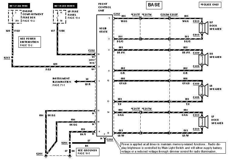
As can be seen by the diagrams below, the radio has two sources of power, one constant hot, the other a switched power source.


If the Y/BK(yellow with small black stripe) wire on the radio harness is cut and the side of the wire that connects to the back of the radio connected relay pair shown previously, one could listen to the radio for around 30 minutes after the ignition was turned off or until a door is opened.

Some installers would just connect the LG/Y wire of the radio to the constant hot wire on the radio harness. While this does allow one to listen to the radio without the keys in the ignition, it also allows the radio to play until the vehicles battery is completely discharged. By contrast, with the modification discussed in this article, if the vehicle operator forgets about leaving the radio on, the radio will turn off immediatetly upon exiting the car. If the battery is in decent shape and the ambient air temperature is not exceptionally cold, the battery should have enough reserve capacity in it to power the radio for 30 minutes at reasonable volume levels and still have enough power left to start the car later in the day.

If a remote starter system is installed in the vehicle that energizes the accessory circuit, the radio and other power accessories will time out after 30 minutes has elapsed since the remote start sequence terminated. If you desire to immediatetly have the radio shut off upon the remote start sequence termination or upon locking the doors, send a momentary ground pulse to the door trigger input of the relay pair. Remember to diode isolate the door lock pulses to prevent the door lock relays from catching a ground path through the door ajar switches.


Above is the power distribution circuit from a 98' crownvic. The power window motors can draw close to 10 amps per window when moving and the crown vic is a 4 door car with 4 windows. So connecting the window switches through the demand lighting output is going to draw too much power through the lcm.
 
 
When the ignition switch is turned to the run or accessory postions, the switch electrically connects the BR (brown) wire with the BK/LG (black with light green stripe) wire. But the problem with jumpering the BR and BK/LG wires on the ignition switch harness together is that the lcm also recieves an input from the this branch of the ignition switch harness and will create a feedback loop disabling the 30 minute timer. Solution is to get power from the BR ignition switch harness and individually apply it to the circuits that are desired to be powered after the ignition switch is turned off.


I found the middle of the dashboard to be an undesirable location for a trunk release button and decided to retask it so that pushing the button would again latch the relays and allow one to listen to the radio for another few minutes. There are two power trunk release connectors above the climate control head on police interceptors. Connecting one of the connectors to the switch results in a trunk release switch that works regardless of whether the keys are in the ignition, connecting the other to the trunk release button results in a trunk release button that only works when the key is in the run or accessory positions. For this project, select the constant hot connector with the BK/W (black with white stripe) wire and the P/Y (purple with yellow stripe) wire. Cut the purple with yellow stripe wire and connect the end that runs into the switch to the relay pair pictured at the beginning of the article harness and cover the unused end with electrical tape.


The drivers and passenger door ajar wires are avaliable at the lcm and behind the drivers kickpanel. The blue wire is for the drivers door, the black/orange wire is for the remaining three passenger's doors. Make sure to use an appropriate number of diodes to prevent the relays from providing false door ajar signals to lcm.

Alternatively, pin 10 highlighted in the diagram above provides a low current ground path whenever one or more of the doors is ajar. This output is used for the digital dash door ajar light and for the air suspension suspension system, but if a connector pin is inserted into this location it could be used for the delayed accessory project too.


The demand lighting output is present at multiple locations throughout the vehicle including behind the drivers kickpanel, but it can be tapped at the back of the lcm too.


Questions or Comments?

Email Me: [email protected]